catalog
instruction manual
software
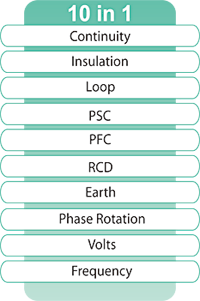


Continuity Measurement
Continuous testing can be carried out by use of the test button lockdown feature. A selectable buzzer gives instantaneous indication of continuity. Null facility eliminates the test lead resistance from the results, the nulled value is retained even if the instrument is switched off. Live circuit warnings are given by a flashing LED, buzzer and indication on the display.
Insulation Measurement
Three selectable test voltages 250V, 500V and 1000V. An auto-discharge function ensures that circuits are not hazardous after testing. A red LED gives warning of high voltage output during testing and discharging of the circuit. In case of connecting to a live circuit, a live circuit warning is given by flashing LED, buzzer and indication on the display.
Loop Impedance Measurement
A patented (ATT) low current loop impedance test enables high accuracy loop measurements and quick testing without tripping RCD’s.
A high current alternative is selectable for even higher accuracy and instantaneous results. The subsequent test will default to the low current test, this saves any inadvertent tripping of the RCD. The KEW 6016 allows also for phase to phase loop tests.
PSC / PFC Measurement
The Prospective Short Circuit Current (PSC) and Prospective Fault Current (PFC) are automatically calculated and shown on the display. As loop testing, the function has low and high test current options with the default to low current to avoid inadvertent tripping of RCDs.
RCD Measurement
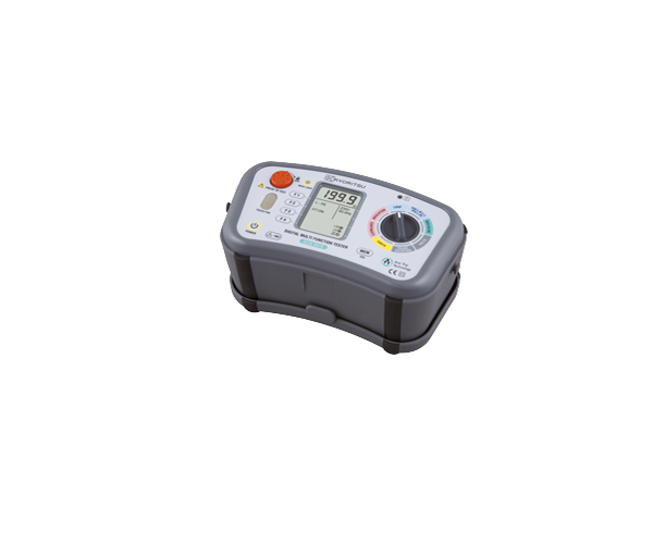
The KEW 6016 has a comprehensive RCD test feature for RCD type AC (Alternative Currents), RCD type A (Pulsating Direct Currents), General and Selective (delayed).
Measures at 1/2x, 1x, 5x of nominal RCD current. It also has Ramp Test and Auto test where all results are shown on one screen. Touch voltage limit can be selected for 25V or 50V depending on application.
Earth Measurement
Using the classical Volt-Amper method with two auxiliary earth spikes and without external power source. All test leads and spikes are supplied as standard accessories.
Phase rotation
KEW 6016 can check the phase rotation of three phase lines with clear indication of the sequence on the display.
Voltage Measurement
In addiction to the voltage measurement, this function gives also the Frequency of the voltage under test.
| Continuity | ||||||||
|---|---|---|---|---|---|---|---|---|
| Range | 20/200/2000Ω (Auto-ranging) | |||||||
| Open circuit voltage (DC) |
5V±20% (*1) | |||||||
| Short circuit current |
Greater than 200mA | |||||||
| Accuracy | ±0.1Ω (0 – 0.19Ω) ±2%rdg+8dgt (0.2 – 2000Ω) |
|||||||
| Insulation Resistance | ||||||||
| Range | 20/200MΩ (Auto-ranging) |
20/200/2000MΩ (Auto-ranging) | ||||||
| Open circuit voltage (DC) |
250V+25% -0% | 500V+25% -0% | 1000V+20% -0% | |||||
| Rated current | 1mA or greater @ 250kΩ |
1mA or greater @ 500kΩ |
1mA or greater @ 1MΩ |
|||||
| Accuracy | ±2%rdg+6dgt (0 – 19.99MΩ) ±5%rdg+6dgt (20 – 200MΩ) |
±2%rdg+6dgt (0 – 199.9MΩ) ±5%rdg+6dgt (200 – 2000MΩ) |
||||||
| Loop Impedance | ||||||||
| Function | L-PE | L-PE (ATT) | L-N / L-L | |||||
| Rated Voltage | 100 – 260V 50/60Hz | L-N: 100 – 300V L-L: 300 – 500V 50/60Hz |
||||||
| Nominal Test Current at 0Ω External Loop: Magnitude/ Duration (*2) |
20Ω: 6A/20ms 200Ω: 2A/20ms 2000Ω: 15mA/500ms |
L-N: 6A/60ms N-PE: 10mA/approx. 5s |
20Ω: 6A/20ms | |||||
| Range | 20/200/2000Ω (Auto-ranging) |
20/200/2000Ω (Auto-ranging) (L-N < 20Ω) |
20Ω | |||||
| Accuracy | ±3%rdg+4dgt(*3) ±3%rdg+8dgt(*4) |
±3%rdg+6dgt (*3) ±3%rdg+8dgt(*4) |
±3%rdg+4dgt (*3) ±3%rdg+8dgt(*4) |
|||||
| PSC (L-N / L-L) / PFC (L-PE) | ||||||||
| Function | PSC | PFC | PFC (ATT) | |||||
| Rated Voltage | 100 – 500V 50/60Hz | 100 – 260V 50/60Hz | ||||||
| Nominal Test Current at 0Ω External Loop: Magnitude/ Duration (*5) |
6A/20ms | 6A/20ms 2A/20ms 15mA/500ms |
L-N: 6A/60ms N-PE: 10mA/approx. 5s |
|||||
| Range | 2000A/20kA Auto-Ranging | |||||||
| Accuracy | PSC / PFC accuracy is derived from measured loop impedance specification and measured voltage specification |
|||||||
| RCD | ||||||||
| Function | X1/2 | X1 | X5 | Ramp | Auto | |||
| Trip current setting |
10/30/100/300/ 500/1000mA |
10/30/ 100mA |
10/30/ 100/300/ 500mA |
Depending on the accuracy at each function. Measurement sequence: X1/2 0°→X1/2 180° →X1 0°→X1 180° →X5 0°→X5 180° Measurements with x5 are not carried out for RCDs with nominal current of 100mA or more. |
||||
| Trip current Duration |
2000ms | G: 550ms S: 1000ms |
410ms | Goes up by 10% from 20% to 110% G:300ms/ S:500ms X10 times |
||||
| Rated Voltage | 230V+10%-15% 50/60Hz | |||||||
| Accuracy | AC Type: -8% – -2% A Type: -10% – 0% |
AC Type: +2% – +8% A Type: 0% – +10% |
AC Type: ±4% A Type: ±10% |
|||||
| Trip time: ±1%rdg+3dgt | ||||||||
| RCD (Uc) | ||||||||
| Function | UC | |||||||
| Rated Voltage | 230V+10% – 15% 50/60Hz | |||||||
| Range | 100.0V | |||||||
| Test current | ≤ 1/2IΔn (max150mA) | |||||||
| Accuracy | +5% – +15%rdg, ±8dgt | |||||||
| Earth | ||||||||
| Range | 20/200/2000Ω Auto-Ranging | |||||||
| Accuracy | 20Ω: ±3%rdg+0.1Ω 200/2000Ω: ±3%rdg+3dgt (Auxiliary earth resistance 100±5%) |
|||||||
| Phase Rotation | ||||||||
| Rated Voltage | 50-500V 50/60Hz | |||||||
| Remarks | Correct phase sequence: are displayed “1.2.3” and Reversed phase sequence: are displayed “3.2.1” and |
|||||||
| Volts | ||||||||
| Function | Volts | Frequency | ||||||
| Rated Voltage | 25 – 500V, 45 – 65Hz | |||||||
| Measuring range | 25 – 500V | 45 – 65Hz | ||||||
| Accuracy | ±2%rdg+4dgt | ±0.5%rdg+2dgt | ||||||
| Applicable standards | IEC 61010-1 CAT III 300V (500V L to L) Pollution degree 2, IEC 61010-031, IEC 61557-1, 2, 3, 4, 5, 6, 7, 10, IEC 60529 (IP40), IEC 61326 (EMC) |
|---|---|
| Power source | LR6 X 8 |
| Dimensions | 136(L) X 235(W) X 114(D)mm |
| Weight | 1350g (including batteries.) |
| Included Accessories | 7188A (Distribution board fuse test lead set) 7281 (Test leads with remote control switch) 7218A (Power cord [EU]) (*6) 7228A (Earth resistance test leads) 8032 (Auxiliary earth spikes) 8212-USB (USB adaptor with KEW Report (Software)) 9084 (Cord case) 9142 (Carrying case) 9121 (Shoulder strap) Cord case, Buckle, Battery, Instruction manual |
| Optional Accessories | 8212-RS232C (RS232C adaptor with KEW Report (Software)) |
(*1): Voltages are output when measurement resistance is under 2100 ohm.
(*2): at 230V
(*3): 230V+10%-15%
(*4): voltages except for (*3)
(*5): at 230V
(*6): 7187A (Power cord [UK]), 7221A (Power cord [SA]), 7222A (Power cord [AU])

