
Loggers KEW 5010
Thương hiệu :
Kyoritsu
Cam kết và Chính sách của TECHNO
-

Cam kết 100% Hàng chính hãng
-

Chất lượng cao, đáp ứng đa dạng nhu cầu
-

Tư vấn kỹ thuật toàn diện và chuyên sâu
-

Chính sách bảo hành và hỗ trợ nhanh chóng
catalog
instruction manual
applicable model list
software
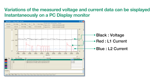
3 channel inputs for the simultaneous recording of Leakage Current and Load Current
• Large capacity for storing 60,000 data points
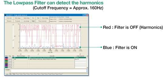
• Lowpass Filter will filter out the harmonics
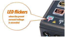
• LED flickers when the preset current value is exceeded
• CALL: Confirmation of recorded data
• Selection of One-time mode or Endless mode
• Non Volatile Memory
• Battery power indicator
• The userfriendly PC software “KEW LOG Soft 2” is supplied
• Continuous measuring time: Approx. 10 days (Alkaline Battery)


Application Notes and Useful Tips
Insulation Level Monitoring by checking the leakage current
- Detect an intermittent leakage current as often this is unpredictable.
- Check for nuisance tripping of an RCD/ELCB due to a leakage current. Check also if RCD is tripping at its rated tripping current.
- Check for the presence of harmonics. Use 2 clamp sensors (one per channel) on same line and use the filter function on one clamp sensor. A difference in values between the 2 channels will indicate the presence of harmonics. In this way the source generating harmonics can be traced.
Monitoring the load current
- Confi rm the stability of a load (eg. motor) and the distortion it causes to the current by detecting accurately the over load caused for example by an inrush (starting) current and a surge current.
- Check for phase imbalance (in a 3 phase system)
- Rate switchgear appropriately by measuring the peak current and the inrush current.
- Analyze voltage drop due to starting current and thus compensate accordingly.
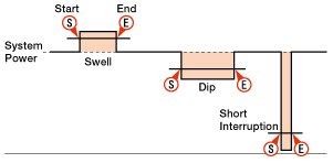
Monitoring voltage fluctuation (Power quality analysis)
- Measure/ record the reference voltage, swell, dip, short interruption.
- Locate the source of voltage drop caused by the operation of large motors in industrial applications.
Eg. In the event of a voltage drop at the load side:
1. If current remains stable, then the source will be upstream with respect to the load.
2. If the current increases, then the source will be down stream with respect to the load. - Check out on machine (eg. welding robot, heavy mechanical electric machine) downtime/stoppages caused by abnormal voltage fl uctuations.
Monitoring overall electrical power of production line at factories or each floor at buildings
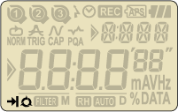
4 recording modes make various measurements possible
![]() Normal recording mode
Normal recording mode
For monitoring power line status or an intermittent leakage.
- Records the variation of the current / voltage in a given interval (For monitoring the variation of the current / voltage against time.)
- A choice of 15 recording intervals are available: 1 sec. to 60 min.
(1,2,5,10,15,20,30 sec, 1,2,5,10,15,20,30,60 min.) - The average of the measured value in every recording interval is recorded. The Max., Min. and Peak values (sampled crest value converted to sine RMS value) are recorded every 10 readings.

![]() Trigger recording mode
Trigger recording mode
For observing an irregular operation of an ELCB/RCD, an irregular current / voltage.
- Detects the value, time and frequency of the current / voltage when the preset value is exceeded.
- When the detection level (i.e. preset value) is exceeded, 8 data points (True RMS values for approx. 0.8 sec) and peak value are recorded before and after the preset value is exceeded.
- Inrush current or an abnormal current / voltage can be detected by sampling the inputs at every 1.6ms.
- LED flickers when the measured values exceed the preset current / voltage value.

![]() Capture recording mode
Capture recording mode
For observing waveforms easily.
- Waveform display via a PC by sampling the inputs every 0.55ms.
- When the preset current / voltage value is exceeded, instantaneous values are recorded for 200ms (from 10(50Hz) to 12 (60Hz) waveforms) before and after preset value is exceeded.
- LED flickers when the measured values exceed the preset current / voltage value.

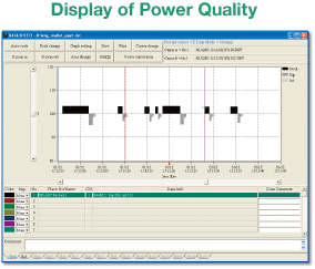
![]() Power Quality Analysis mode
Power Quality Analysis mode
For monitoring and observing voltage fluctuations.
- Detects the reference voltage, Swell, Dip and Short Interruption. Records the values detected with the start time and end time.
- Samples the inputs every 0.55ms and detects the voltage fl uctuation every 10ms.
- LED fl ickers when the voltage fl uctuation is detected.
Large capacity for storing 60,000 data points
60,000 data points can be recorded when 1ch is used, and when all the three channels are used, 20,000 data points per channel can be recorded.
MAX.number of recorded data
| Using all 3 channels | Using 2 channels | Using only 1 channel |
|---|---|---|
| 20,000 data | 30,000 data | 60,000 data |
Max. recording duration
| Recording interval |
Using all 3 channels | Using 2 channels | Using only 1 channel |
|---|---|---|---|
| 1 sec. | 5:33:20 | 8:20:00 | 16:40:00 |
| 2 sec. | 11:06:40 | 16:40:00 | 1 day 9:20:00 |
| 5 sec. | 1 day 3:46:40 | 1 day 17:40:00 | 3 days 11:20:00 |
| 10 sec. | 2 days 7:33:20 | 3 days 11:20:00 | 6 days 22:40:00 |
| 15 sec. | 3 days 11:20:00 | 5 days 5:00:00 | 10 days 10:00:00 |
| 20 sec. | 4 days 15:06:40 | 6 days 22:40:00 | 13 days 21:20:00 |
| 30 sec. | 6 days 22:40:00 | 10 days 10:00:00 | 20 days 20:00:00 |
| 1 min. | 13 days 21:20:00 | 20 days 20:00:00 | 41 days 16:00:00 |
| 2 min. | 27 days 18:40:00 | 41 days 16:00:00 | 83 days 8:00:00 |
| 5 min. | 69 days 10:40:00 | 104 days 4:00:00 | 208 days 8:00:00 |
| 10 min. | 138 days 21:20:00 | 208 days 8:00:00 | 416 days 16:00:00 |
| 15 min. | 208 days 8:00:00 | 260 days 10:00:00 | 520 days 0:00:00 |
| 20 min. | 277 days 18:40:00 | 416 days 16:00:00 | 833 days 8:00:00 |
| 30 min. | 416 days 16:00:00 | 625 days 0:00:00 | 1250 days 0:00:00 |
| 60 min. | 833 days 8:00:00 | 1250 days 8:00:00 | 2500 days 0:00:00 |
Continuous measuring time : Approx. 10 days (Alkaline Battery)
* Max recording time is dependent on battery life (approx 10-days with Alkaline battery)
* Use of optional AC Adopter is recommended for long time recording.
LED flickers when the preset current / voltage value is exceeded.
- Available for Trigger / Capture Recording, Power Quality Analysis modes.
- LED on the Sensor connected channel blinks when following Trigger is detected.
- LED flashes whenever the measured values exceed the pre-set detection level during measurements.
Trigger is detected when the measured values exceed the pre-set detection level under Trigger / Capture Recording Mode and Power Quality Analysis Mode.
For voltage values, Trigger is detected when it is below the detection level.
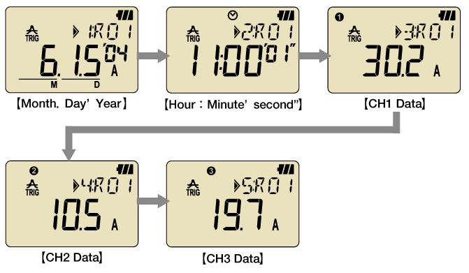
CALL : Confirmation of recorded data
- The following can be displayed: number of recorded data points, (max+ min+ peak) value for each channel complete with time/date information in the Normal recording mode. (Detected values (i.e. when values are outside preset limits) can be displayed in other recording modes)
- RECALL: The last 10 recorded data points including time/date can be recalled on the logger display.
Selection of One-time mode or Endless mode
- One-time on:

Recording will stop when memory is used up. - One-time off:

Over write the old data, and store the latest data.
Battery power indicator
- Indicates battery voltage in 4-levels.
(It is possible to use the logger for a further approx 24 hours even after the warning symbol is fl ashing.)
- Recorded data will be retained even if the batteries are exhausted or replaced due to the presence of a nonvolatile memory (guaranteed for 10 years)
Analyzing and processing the recorded data with a PC
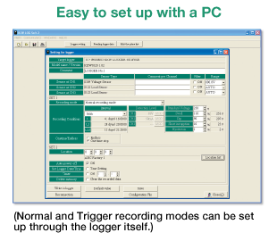
Easy to set up with a PC
- Supplied with the user friendly software “KEW LOG Soft 2”.
- The recorded data is downloadable onto a PC via USB cable.
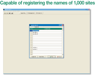
- Via the software the following parameters can be set: time/date, recording intervals, the start of recording, recording methods, name of monitoring site and comments.
- The type of the sensor connected to the logger will be automatically recognized.
- Just click appropriate dialog boxes for set up if it is not required to input any comments.
- By using commercially available USB hub, multiple loggers can be connected to a PC and can set the synchronized time.
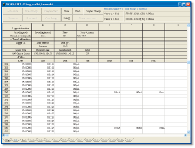
Large data can be easily processed
- Recorded data can also be converted to CSV files, and data can be processed in Excel.
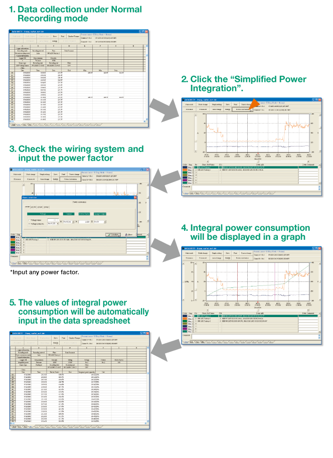
Graphical display
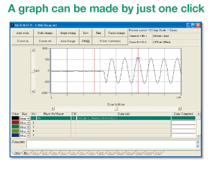
Simplified Power Integration
- The PC software “KEW LOG Soft 2” provides easy calculation of integral power consumption.
(Single-phase 2-wire, Single-phase 3-wire, Three-phase 3-wire, Threephase 4-wire)
* Simplifi ed power integration function is available for the data recorded under Normal Recording mode.
KEW LOG Soft2
【System requirements】
| OS | Windows® 8/10 |
|---|---|
| Display | XGA (1024×768 dots) or more |
| Hard-disk | Space required 100Mbyte or more |
| Others | With CD-ROM drive and USB port |
Normal Recording Mode
(AC 50/60Hz, Sine wave, Input: 10% or more of the range at CH1)
| Range | RMS Accuracy |
|---|---|
| 100.0mA | ±2.0%rdg±0.9%f.s.+ Accuracy of Sensor |
| Other ranges | ±1.5%rdg±0.7%f.s.+ Accuracy of Sensor |
| Crest Factor | 2.5 or less: RMS accuracy (sine) + 2%rdg + 1%f.s. |
*Max, Min and Instant Peak values in Normal Recording mode are just reference values: their accuracies aren’t guaranteed.
Trigger Recording Mode (AC 50/60Hz sine wave)
| Range | Accuracy |
|---|---|
| 100.0mA | ±3.5%rdg±2.2%f.s.+ Accuracy of Sensor |
| Other ranges | ±3.0%rdg±2.0%f.s.+ Accuracy of Sensor |
Capture Recording Mode
| Range | Accuracy |
|---|---|
| 100.0mA | ±3.0%rdg±1.7%f.s.+ Accuracy of Sensor |
| Other ranges | ±2.5%rdg±1.5%f.s.+ Accuracy of Sensor |
| Recording mode | Normal, Trigger, Capture |
|---|---|
| Operating system | Successive Approximation (CH1 single synchronized sampling) |
| Rated max. working voltage | AC 9.9Vrms, 14V peak value |
| Number of input channel | 3ch |
| Measuring method | True RMS |
| RMS measuring interval | approx. 100ms |
| Sampling interval | Normal/Trigger mode : approx. 1.65ms/CH Capture mode : approx. 0.55ms (waveform: at every 1.1ms) |
| Current range | 8146 (30A type) : 100.0/1000mA/10.00/30.0A 8147 (70A type) : 100.0/1000mA/10.00/70.0A 8148 (100A type) : 100.0/1000mA/10.00/100.0A 8121 (100A type) : 10.00/100.0A 8122 (500A type) : 50.00/500.0A 8123 (1000A type) : 100.0/1000A 8128/8135 (5A type) : 5.000A/(50.00A) 8127 (100A type) : 10.00A/100.0A 8126 (200A type) : 20.00A/200.0A 8125 (500A type) : 50.00A/500.0A 8124 (1000A type) : 100.0A/1000A 8130 (1000A type) : 100.0/1000A |
| Low battery warning | Battery mark display (in 4 levels) |
| Over-range indication | “OL” mark is displayed when exceeding the measuring range |
| Auto power off | Power-off function operates automatically after a switch remains for 3min. (when recording is stopped) |
| Possible measurement time | Approx. 10 days (with alkaline LR6 batteries) |
| Applicable standards | IEC 61010-1:2001 CAT III 300V Pollution degree2 IEC 61326 (EMC standard) |
| Dimensions | 111(L)×60(W)×42(D)mm |
| Weight | Approx. 265g |
| Included Accessories | 7148 (USB cable), 9118 (Carrying case) Alkaline battery LR6×4pcs, PC software “KEW LOG Soft 2”, Instruction manual, Quick manual, Install manual, USB Notice sheet |
| Optional Accessories | 8146/8147/8148 (Leakage & Load current Clamp Sensor), 8121/8122/8123 (Load current Clamp Sensor), 8124/8125(*1)/8126(*2)/8127(*3)/8128 (Load current Clamp Sensor), 8130(*4)/8135 (Flexible Clamp Sensor), 7185 (Extension cable for sensor) 8320 (AC Adapter), 9135 (Carrying bag) |
*1-4: Can use with after the following serial numbers.
*1:8125 No.02637-
*2:8126 No.00151-
*3:8127 No.00181-
*4:5010 No.8029792-
Sản phẩm tương tự


Bài viết liên quan

Tin kỹ thuật
Kính hiển vi Motic: Nguyên lý hoạt động, cấu tạo và tiêu chí lựa chọn
Kính hiển vi Motic là thiết bị quan sát được ứng dụng rộng rãi trong phòng thí nghiệm, y tế và công nghiệp. Với công nghệ quang học tiên tiến, thiết kế bền bỉ và khả năng ứng dụng đa dạng, dòng kính này ngày càng được nhiều doanh nghiệp và phòng thí nghiệm lựa chọn. Trong bài viết này, hãy cùng Techno tìm hiểu kính hiển vi Motic là gì, nguyên lý hoạt động, cấu tạo và tiêu chí…
29/04/2026
Đọc
thêm

Tin kỹ thuật
Ứng dụng ICT trong sản xuất điện tử – Giải pháp tối ưu thời 4.0
Trong bối cảnh ngành điện tử ngày càng yêu cầu cao về độ chính xác, tốc độ và chất lượng, việc kiểm soát lỗi ngay từ khâu sản xuất PCB trở thành yếu tố then chốt. Do đó, ứng dụng ICT trong sản xuất điện tử ngày càng được các doanh nghiệp ưu tiên triển khai nhằm phát hiện lỗi sớm, tối ưu chi phí và nâng cao hiệu quả vận hành. Hãy cùng Techno tìm hiểu ứng dụng ICT…
29/04/2026
Đọc
thêm
Tin sản phẩm
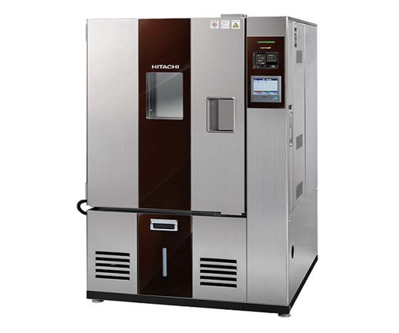
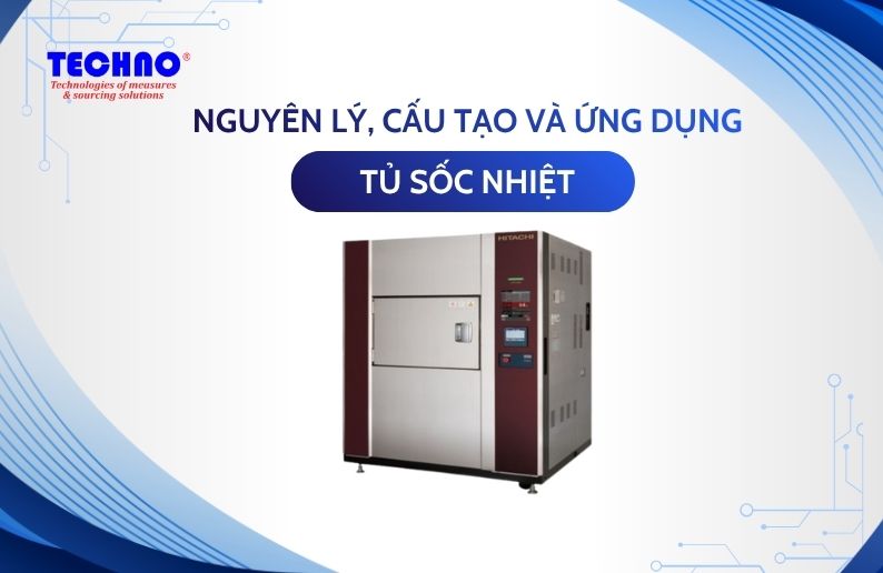
Tủ sốc nhiệt: Nguyên lý hoạt động, cấu tạo và ứng dụng thực tế
Trong quy trình sản xuất linh kiện điện tử, ô tô và hàng không vũ trụ, khả năng chịu đựng sự thay đổi nhiệt độ đột ngột là yếu tố quan trọng quyết định chất lượng sản phẩm. Tủ sốc nhiệt chính là giải pháp mô phỏng hoàn hảo các điều kiện khắc nghiệt này, giúp doanh nghiệp đánh giá độ bền và ngăn ngừa rủi ro hỏng hóc sớm. 1. Tủ sốc nhiệt là gì? Tủ sốc nhiệt (Thermal…
29/04/2026
Đọc
thêm

Tin sản phẩm
Buồng thử nghiệm môi trường: Giải pháp kiểm soát chất lượng sản phẩm
Trong kỷ nguyên sản xuất hiện đại, một sản phẩm tốt không chỉ nằm ở tính năng mà còn ở độ bền bỉ dưới mọi tác động khắc nghiệt của thời tiết. Buồng thử nghiệm môi trường chính là "thước đo" chính xác nhất giúp doanh nghiệp kiểm soát rủi ro, tối ưu hóa vật liệu và chinh phục những tiêu chuẩn quốc tế khắt khe nhất. 1. Buồng thử nghiệm môi trường là gì? Buồng thử nghiệm môi trường…
29/04/2026
Đọc
thêm
Tin sản phẩm
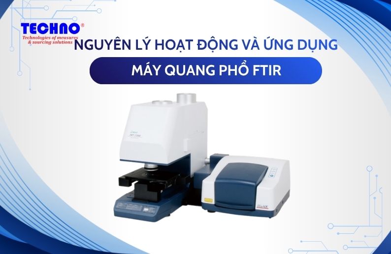
Máy quang phổ FTIR là gì? Nguyên lý hoạt động và ứng dụng chi tiết
Trong lĩnh vực phân tích vật liệu và kiểm soát chất lượng, việc xác định chính xác thành phần hóa học đóng vai trò quan trọng trong nghiên cứu và sản xuất. Máy quang phổ FTIR là một trong những thiết bị được sử dụng phổ biến nhờ khả năng phân tích nhanh, chính xác và không phá hủy mẫu. Vậy máy quang phổ FTIR là gì, hoạt động theo nguyên lý nào và được ứng dụng ra sao trong…
29/04/2026
Đọc
thêm